Remote sensing of the earth. Remote sensing data Remote sensing methods in geology
Send your good work in the knowledge base is simple. Use the form below
Students, graduate students, young scientists who use the knowledge base in their studies and work will be very grateful to you.
Hosted at http://www.allbest.ru/
1. Basic concepts of remote sensing of the Earth. Remote sensing scheme
remote sensing earth geodetic
Remote sensing of the Earth (ERS) - obtaining information about the surface of the Earth and objects on it, the atmosphere, the ocean, the upper layer of the earth's crust by non-contact methods, in which the recording device is removed from the object of research at a considerable distance.
The physical basis of remote sensing is the functional relationship between the registered parameters of the object's own or reflected radiation and its biogeophysical characteristics and spatial position.
Remote sensing is used to study the physical and chemical properties of objects.
There are two interrelated directions in remote sensing
Natural science (remote research)
Engineering (remote methods)
remote sensing
remote sensing techniques
The subject of remote sensing as a science is the spatio-temporal properties and relationships of natural and socio-economic objects, manifested directly or indirectly in their own or reflected radiation, remotely recorded from space or from the air in the form of a two-dimensional image - a snapshot.
Remote sensing methods are based on the use of sensors that are placed on spacecraft and register electromagnetic radiation in formats that are much more suitable for digital processing, and in a much wider range of the electromagnetic spectrum.
In remote sensing, the infrared range of reflected radiation, thermal infrared and radio range of the electromagnetic spectrum are used.
The process of collecting remote sensing data and using it in geographic information systems (GIS).
2. Types of space surveys
Space photography occupies one of the leading places among the various methods of remote sensing. It is carried out using:
* artificial satellites of the Earth (ISS),
* interplanetary automatic stations,
* long-term orbital stations,
* manned spacecraft.
Tab. The main spaceports used for launching surveyor satellites.
Space systems (complexes) for monitoring the environment include (and perform):
1. Satellite systems in orbit (mission and survey control center),
2. Reception of information by ground receiving points, relay satellites,
3. Storage and distribution of materials (primary processing centers, image archives). An information retrieval system has been developed that ensures the accumulation and systematization of materials received from artificial Earth satellites.
Orbits of spacecraft.
Carrier orbits are divided into 3 types:
* equatorial,
* polar (pole),
* oblique.
Orbits are divided into:
* circular (more precisely, close to circular). Satellite images obtained from a space carrier that moved in a circular orbit have approximately the same scale.
* elliptical.
Orbits are also distinguished by their position relative to the Earth or the Sun:
* geosynchronous (relative to the Earth)
* heliosynchronous (relative to the Sun).
Geosynchronous - a spacecraft moves with an angular velocity equal to the speed of the Earth's rotation. This creates the effect of the space carrier “hovering” at one point, which is convenient for continuous surveys of the same area of the earth's surface.
Heliosynchronous (or sun-synchronous) - a spacecraft passes over certain areas of the earth's surface at the same local time, which is used in the production of multiple surveys under the same lighting conditions. Heliosynchronous orbits - orbits, when shooting from which the solar illumination of the earth's surface (the height of the Sun) remains practically unchanged for quite a long time (almost during the Season). This is achieved in the following way. Since the plane of any orbit, under the influence of the non-sphericity of the Earth, unfolds a little (precesses), it turns out that by choosing a certain ratio of the inclination and height of the orbit, it is possible to achieve that the magnitude of the precession is equal to the daily rotation of the Earth around the Sun, i.e., about 1 ° per day. Among near-Earth orbits, it is possible to create only a few sun-synchronous orbits, the inclination of which is always reversed. For example, at an orbit altitude of 1000 km, the inclination should be 99°.
Shooting types.
Space imaging is carried out by different methods (Fig. "Classification of space images by spectral ranges and imaging technology").
According to the nature of the coverage of the earth's surface by satellite images, the following surveys can be distinguished:
* single photography,
* route,
* sighting,
* global shooting.
Single (selective) photographing is carried out by astronauts with hand-held cameras. Pictures are usually obtained perspective with significant angles of inclination.
Route survey of the earth's surface is carried out along the path of the satellite. The survey swath width depends on the flight altitude and the viewing angle of the imaging system.
Aimed (selective) survey is designed to obtain images of specially specified areas of the earth's surface away from the road.
Global imaging is carried out from geostationary and polar-orbiting satellites. satellites. Four to five geostationary satellites in equatorial orbit provide practically continuous acquisition of small-scale panoramic images of the entire Earth (space patrols) except for the polar caps.
aerospace image
An aerospace image is a two-dimensional image of real objects, which is obtained according to certain geometric and radiometric (photometric) laws by remote registration of the brightness of objects and is intended to study visible and hidden objects, phenomena and processes of the surrounding world, as well as to determine their spatial position.
A space image in its geometric properties does not fundamentally differ from an aerial photograph, but has features associated with:
* photographing from great heights,
* and high speed.
Aerospace photography is performed in the visible and invisible ranges of electromagnetic waves, where:
1. photographic - visible range;
2. non-photographic - visible and invisible ranges, where:
· visible range - spectrometric is based on the difference in the spectral reflection coefficients of geological objects. The results are recorded on magnetic tape and marked on the map. It is possible to use film and photo cameras;
Invisible range: radar (radiothermal RT and radar radar), ultraviolet UV, infrared IR, optoelectronic (scanner), laser (lidar).
Visible and near infrared region. The most complete amount of information is obtained in the most developed visible and near infrared regions. Aerial and space surveys in the visible and near infrared wavelength ranges are carried out using the following systems:
* Television,
* photographic,
* optoelectronic scanning,
3. Photographic systems
Currently, there is a wide class of remote sensing systems
forming an image of the underlying surface under study. Within this class of equipment, several subclasses can be distinguished that differ in the spectral range of the electromagnetic radiation used and in the type of the detected radiation receiver, also according to the active or passive method (photographic and phototelevision sounding systems: scanning systems of the visible and IR ranges, television optical - mechanical and optical-electronic scanning radiometers and multispectral scanners; television optical systems: side-scan radar systems (RLSBO);
Photographic images of the Earth's surface are obtained from manned spacecraft and orbital stations or from automatic satellites. A distinctive feature of space images (CS) is a high degree
visibility Coverage of large surface areas with one image Depending on the type of equipment used and photographic films, photography can be carried out in the entire visible range of the electromagnetic spectrum in its individual zones, as well as in the near IR (infrared) range
The scale of the survey depends on the two most important parameters of the survey height and the focal length of the lens - Depending on the inclination of the optical axis, space cameras allow you to obtain planned and perspective images of the earth's surface. Currently, high-resolution photographic equipment is used that allows you to obtain (CS) with an overlap of 60% or more - The spectral range of photographing covers the visible part of the near infrared zone (up to 0.86 microns). The well-known shortcomings of the photographic method are associated with the need to return the film to Earth and its limited supply on board. However, photographic shooting is currently the most informative type of shooting from outer space - the optimal print size is 18x18 cm, which, as experience shows, is consistent with the physiology of human vision, allowing you to see the entire image at the same time. topographic reference of control points with an accuracy of 0.1 mm or more. For the installation of photo schemes, only planned CSs are used
To bring a multi-scale usually promising CS to a planned one, a special process called transformation is used.
4. Television systems
TV and scanner pictures. Television and scanner photography makes it possible to systematically obtain images and transmit them to Earth at receiving stations. Personnel and scanning systems are used. In the first case, this is a miniature television camera in which the optical image constructed by the lens on the screen is converted into the form of electrical signals and transmitted to the ground via radio channels - In the second case, the swinging mirror of the scanner on board captures the light flux reflected from the Earth, which enters the photomultiplier. The converted scanner signals are transmitted to the Earth via radio channels. At receiving stations, they are recorded as images. Vibrations of the mirror form lines of the image, the movement of the carrier allows you to accumulate lines and form an image. Television and scanner images can be transmitted in real time, i.e. during the passage of the satellite over the subject. Efficiency is the hallmark of this method. However, the quality of the images is somewhat inferior to photographic images. The resolution of scanner images is determined by the scanning element and is currently 80-30 m. Images of this type are distinguished by a line-grid structure that is noticeable only when zoomed in on high-resolution images. Scanner images of large coverage have significant geometric distortions. Scanned images are received in digital form, which facilitates computer processing.
Television and scanner shooting is carried out from meteorological satellites and resource satellites LandSat, Meteor-Priroda, Resource 0. In a multi-zone version.
Earth orbits with a height of 600-1400 km., Scales from 1:10,000,000 to 1:1,000,000 and 1:100,000 with a resolution of 1-2 km to 30 m. LandSat, for example, has 4 spectral imaging ranges in the visible and near infrared range with a resolution of 30 m. "Meteor-Priroda" scanners allow you to get small (1.5 km), medium (230 m) and high resolution up to 80-40 m, Resource -0 medium (170 m) and high (40 m) scanners .
Multi-element CCD images. A further increase in resolution with the speed of shooting is associated with the introduction of electronic cameras. They use multi-element linear and matrix radiation receivers, consisting of charge-coupled devices (light-sensitive detector elements). A linear array of detectors implements a snapshot row, the accumulation of rows due to the movement of the carrier. (similar to a scanner), but no oscillating mirrors and higher resolution. High resolution resource images (40m) Resource and French SPOT satellite, up to 10 m. In phototelevision, photographing with a camera (resulting in good quality), and transmission via television channels - Thus, the advantages of photography with its high resolution and prompt delivery of images are combined.
5. Scanner systems
At present, for surveys from space, multispectral (multispectral) cameras are most often used. optical-mechanical systems - scanners installed on satellites for various purposes. With the help of scanners, images are formed, consisting of many separate, sequentially obtained elements. The term "scanning" means scanning the image using a scanning element (oscillating or rotating mirror), which scans the area element by element across the movement of the carrier and sends a radiant flux to the lens and then to a point sensor that converts the light signal into an electrical one.
This electrical signal is sent to receiving stations via communication channels. The image of the terrain is obtained continuously on a tape composed of stripes - scans, folded by individual elements - pixels. Scanner images can be obtained in all spectral ranges, but the visible and IR ranges are especially effective. When shooting the earth's surface with the help of scanning systems, an image is formed, each element of which corresponds to the brightness of the radiation of the area located within the instantaneous field of view. A scanner image is an ordered packet of brightness data transmitted via radio channels to the Earth, which is recorded on magnetic tape (in digital form) and then can be converted to a frame form. The most important characteristics of the scanner are the scanning (viewing) angle and the instantaneous angle of view, the magnitude of which determines the width of the filmed strip and resolution. Depending on the size of these angles, scanners are divided into accurate and survey. For precision scanners, the scanning angle is reduced to ±5°, and for survey scanners, it is increased to ±50°. The resolution value is inversely proportional to the width of the filmed band. A new generation scanner, called the "thematic cartographer", which was equipped with American satellites, has proven itself well
Landsat 5 and Landsat 7. The “thematic mapper” type scanner operates in seven bands with a resolution of 30m in the visible range of the spectrum and 120m in the IR range. This scanner gives a large flow of information, the processing of which requires more time; in connection with this, the image transmission speed slows down (the number of pixels in the images reaches more than 36 million on each of the channels). Scanning devices can be used not only to obtain images of the Earth, but also to measure radiation scanning radiometers, and scanning radiation - spectrometers.
6. Laser scanning systems
Just ten years ago, it was very difficult to even imagine that they would create a device that could make up to half a million complex measurements in one second. Today, such devices are not only created, but also very widely used.
Laser scanning systems - it is already difficult to do without them in many industries, such as mining, industry, topographic survey, architecture, archeology, civil engineering, monitoring, city modeling and more.
The fundamental technical parameters of terrestrial laser scanners are the speed, accuracy and range of measurements. The choice of model largely depends on the types of work and objects on which the scanners will be used. For example, in large quarries, it is better to use devices with increased accuracy and range. For architectural work, a range of 100-150 meters is quite enough, but a device with an accuracy of 1 cm is required. If we talk about the speed of work, then in this case, the higher, the better, of course.
Recently, ground-based laser scanning technology has been increasingly used to solve engineering geodesy problems in various areas of construction and industry. The growing popularity of laser scanning is due to a number of advantages that the new technology provides compared to other measurement methods. Among the advantages, I would like to highlight the main ones: an increase in the speed of work and a decrease in labor costs. The emergence of new, more productive models of scanners, the improvement of software capabilities, allows us to hope for a further expansion of the scope of terrestrial laser scanning.
The first scan result is a point cloud, which carries the maximum information about the object under study, be it a building, an engineering structure, an architectural monument, etc. Using the point cloud in the future, it is possible to solve various problems:
Obtaining a three-dimensional model of the object;
Obtaining drawings, including drawings of sections;
Identification of defects and various designs by comparison with the design model;
· determination and evaluation of strain values by means of comparison with previously made measurements;
Obtaining topographic plans by the method of virtual survey.
When surveying complex industrial facilities using traditional methods, performers often face the fact that certain measurements are missed during field work. The abundance of contours, a large number of individual objects lead to inevitable errors. The materials obtained by laser scanning carry more complete information about the subject. Before the start of the scanning process, the laser scanner takes panoramic photographs, which significantly increases the information content of the results obtained.
Terrestrial laser scanning technology, used to create three-dimensional object models, topographic plans of complex loaded territories, significantly increases labor productivity and reduces time costs. The development and implementation of new technologies for the production of geodetic works have always been carried out in order to reduce the time of field work. It is safe to say that laser scanning fully complies with this principle.
Terrestrial laser scanning technology is in constant development. This also applies to the improvement of the design of laser scanners, and the development of software functions used to control devices and process the results obtained.
7. Stefan-Boltzmann law
Heated bodies radiate energy in the form of electromagnetic waves of various lengths. When we say that a body is "red-hot", it means that its temperature is high enough for thermal radiation to occur in the visible, light part of the spectrum. At the atomic level, radiation becomes a consequence of the emission of photons by excited atoms. The law describing the dependence of the energy of thermal radiation on temperature was obtained on the basis of an analysis of experimental data by the Austrian physicist Josef Stefan and theoretically substantiated also by the Austrian Ludwig Boltzmann.
To understand how this law works, imagine an atom emitting light in the bowels of the Sun. Light is immediately absorbed by another atom, re-emitted by it - and thus transmitted along the chain from atom to atom, due to which the whole system is in a state of energy balance. In an equilibrium state, light of a strictly defined frequency is absorbed by one atom in one place simultaneously with the emission of light of the same frequency by another atom in another place. As a result, the light intensity of each wavelength of the spectrum remains unchanged.
The temperature inside the Sun drops as you move away from its center. Therefore, as you move towards the surface, the spectrum of light radiation is corresponding to higher temperatures than the ambient temperature. As a result, during repeated emission, according to the Stefan-Boltzmann law, it will occur at lower energies and frequencies, but at the same time, due to the law of conservation of energy, a larger number of photons will be emitted. Thus, by the time it reaches the surface, the spectral distribution will correspond to the temperature of the surface of the Sun (about 5,800 K), and not to the temperature at the center of the Sun (about 15,000,000 K). The energy that comes to the surface of the Sun (or to the surface of any hot object) leaves it in the form of radiation. The Stefan-Boltzmann law just tells us what the radiated energy is. This law is written like this:
where T is the temperature (in kelvins) and y is Boltzmann's constant. It can be seen from the formula that as the temperature rises, the luminosity of the body not only increases, but increases to a much greater extent. Double the temperature and the luminosity will increase 16 times!
So, according to this law, any body that has a temperature above absolute zero radiates energy. So why, one wonders, have not all bodies cooled down to absolute zero for a long time? Why, say, your body, constantly radiating thermal energy in the infrared range, characteristic of the temperature of the human body (slightly more than 300 K), does not cool down?
The answer to this question is actually two parts. Firstly, with food you get energy from outside, which in the process of metabolic assimilation of food calories by the body is converted into thermal energy, which replenishes the energy lost by your body in accordance with the Stefan-Boltzmann law. A dead warm-blooded animal cools down to ambient temperature very quickly, since the energy supply to its body stops.
Even more important, however, is the fact that the law applies to all bodies without exception with a temperature above absolute zero. Therefore, when giving your thermal energy to the environment, do not forget that the bodies to which you give energy - for example, furniture, walls, air - in turn radiate thermal energy, and it is transferred to you. If the environment is colder than your body (as is most often the case), its thermal radiation compensates for only a part of the heat losses of your body, and it makes up for the deficit using internal resources. If the ambient temperature is close to or higher than your body temperature, you will not be able to get rid of the excess energy released in your body during metabolism through radiation. And then the second mechanism comes into play. You begin to sweat, and along with sweat droplets, excess heat leaves your body through the skin.
In the above formulation, the Stefan-Boltzmann law applies only to an absolutely black body, which absorbs all radiation falling on its surface. Real physical bodies absorb only part of the ray energy, and the rest is reflected by them, however, the pattern according to which the specific power of radiation from their surface is proportional to T 4, as a rule, is also preserved in this case, however, in this case, the Boltzmann constant has to be replaced by another coefficient , which will reflect the properties of a real physical body. Such constants are usually determined experimentally.
8. History of remote sensing methods development
Drawn pictures - Photographs - ground phototheodolite survey - Aerial photographs - aerial methods. - The concept of remote sensing appeared in the 19th century. - Subsequently, remote sensing began to be used in the military field to collect information about the enemy and make strategic decisions. - After World War II, remote sensing began to be used for observation for the environment and assessment of the development of territories, as well as in civil cartography.
In the 60s of the XX century, with the advent of space rockets and satellites, remote sensing went into space. -1960 - the launch of reconnaissance satellites as part of the CORONA, ARGON and LANYARD programs. -Program Mercury - received images of the Earth. Project Gemini (1965-1966) - systematic collection of remote sensing data. Apollo program (1968-1975) - remote sensing of the earth's surface and landing a man on the Moon - Launch of the Skylab space station (1973-1974), - exploration of earth resources. Flights of space shuttles (1981). Obtaining multi-zone images with a resolution of 100 meters in the visible and near infrared range using nine spectral channels.
9. Elements of orientation of space images
The position of the image at the moment of photographing is determined by three elements of internal orientation - the focal length of the camera f, the coordinates x0, y0 of the main point o (Fig. 1) and six elements of external orientation - the coordinates of the projection center S - XS, YS, ZS, the longitudinal and transverse tilt angles of the image b and u and angle of rotation h.
There is a connection between the coordinates of the object point and its image in the image:
where X, Y, Z and XS, YS, ZS are the coordinates of points M and S in the OXYZ system; X", Y", Z" - coordinates of the point m in the SXYZ system parallel to OXYZ, calculated from the x and y plane coordinates:
a1 \u003d cos bcosch - sinbsinschsinch
a2 \u003d - cossinch - sinbsin schcosch
a3 \u003d - sinаcos u
b2 = cosschcosch (3)
c1 \u003d sinbcosch + cosbsinschsinch,
c2 \u003d - sinbcosch + cosbsinschcosch,
Direction cosines.
The formulas for the connection between the coordinates of the point M of the object (Fig. 2) and the coordinates of its images m1 and m2 on the stereopair P1 - P2 have the form:
BX, BY and BZ - projections of the basis B on the coordinate axes. If the exterior orientation elements of the stereopair are known, then the coordinates of the object point can be determined by formula (4) (direct resection method). Using a single image, the position of an object's point can be found in the particular case when the object is flat, for example, flat terrain (Z = const). The x and y coordinates of the image points are measured using a monocomparator or a stereocomparator. Interior orientation elements are known from camera calibration results, and exterior orientation elements can be determined when photographing an object or during phototriangulation (See Phototriangulation). If the exterior orientation elements of images are unknown, then the coordinates of the object point are found using reference points (resection method). Reference point - a contour point of an object identified in the image, the coordinates of which are obtained as a result of geodetic measurements or from phototriangulation. Using a resection, first determine the elements of the relative orientation of the images P1 - P2 (Fig. 3) - b "1, h" 1, a "2, y" 2, h "2 in the S1X"Y"Z" system; the X axis of which coincides with the basis, and the Z axis lies in the main basal plane S1O1S2 of the image P1. Then the coordinates of the points of the model are calculated in the same system. Finally, using anchor points, transition. from model point coordinates to object point coordinates.
Relative orientation elements allow you to set the images in the same position relative to each other that they occupied when photographing the object. In this case, each pair of respective rays, for example S1m1 and S2m2, intersect and form a point (m) of the model. The set of rays belonging to the image is called a ligament, and the projection center - S1 or S2 - is called the vertex of the ligament. The scale of the model remains unknown because the distance S1S2 between the vertices of the ligaments is chosen arbitrarily. The corresponding points of the stereopair m1 and m2 are in the same plane passing through the S1S2 basis. Therefore
Assuming that the approximate values of the relative orientation elements are known, we can represent equation (6) in a linear form:
a db1" + b db2" + s dsch2" + d dch1" + e dch2" + l = V, (7)
where db1",... e dm2" are corrections to the approximate values of the unknowns, a,..., e are the partial derivatives of the function (6) with respect to the variables b1",... h2", l is the value of the function (6) , calculated from approximate values known to me. To determine the elements of relative orientation, the coordinates of at least five points of the stereopair are measured, and then equations (7) are compiled and solved by the method of successive approximations. The coordinates of the points of the model are calculated according to formulas (4), choosing the length of the basis B arbitrarily and assuming
Xs1 = Ys1 = Zs1 = 0, BX = B, BY = BZ = 0.
In this case, the spatial coordinates of the points m1 and m2 are found by formulas (2), and the direction cosines are found by formulas (3): for the image P1, by the elements b1",
and for the snapshot P2 by the elements b2", w2", h2".
According to the X" Y" Z" coordinates, the model points determine the coordinates of the object point:
where t is the denominator of the model scale. Direction cosines are obtained by formulas (3), substituting instead of the angles b, u and h the longitudinal angle of the model o, the transverse angle of the model z and the angle of rotation of the model u.
To determine the seven elements of the exterior orientation of the model - Posted at http://www.allbest.ru/
O, z, u, t - make equations (8) for three or more reference points and solve them. The coordinates of the control points are found by geodetic methods or by the method of phototriangulation. The set of points of the object, the coordinates of which are known, forms a digital model of the object, which serves to draw up a map and solve various engineering problems, for example, to find the optimal road route. In addition to analytical methods for processing images, analog ones are used, based on the use of photogrammetric devices - Phototransformer, Stereograph, Stereoprojector, etc.
Slit and panoramic photographs, as well as photographs obtained with the use of radar, television, infrared-thermal, and other imaging systems, significantly expand the possibilities of photographic imaging, especially in space research. But they do not have a single projection center, and their external orientation elements are continuously changing in the process of imaging, which complicates the use of such images for measurement purposes.
10. Properties of aerospace images
Aerospace images are the main result of aerospace surveys, which use a variety of aviation and space media. This is a two-dimensional image of real objects, which was obtained according to certain geometric and radiometric (photometric) laws by remote registration of the brightness of objects and is intended to study visible and hidden objects, phenomena and processes of the surrounding world, as well as to determine their spatial position. Aerospace surveys are divided into passive ones, which provide for the registration of reflected solar or Earth's own radiation; active, in which registration of reflected artificial radiation is performed. Scale range of aerospace images: from 1:1000 to 1:100,000,000
The most common scales: aerial photographs 1:10,000 - 1:50,000, space - 1:200,000 - 1:10,000,000.
Aerospace images: analog (usually photographic), digital (electronic). The image of digital photographs is formed from separate identical elements - pixels (from the English picture element - pxel); the brightness of each pixel is characterized by one number. Properties of aerospace images: Graphic, Radiometric (photometric), Geometric.
Visual properties characterize the ability of photographs to reproduce fine details, colors and tonal gradations of objects.
Radiometric ones testify to the accuracy of the quantitative registration of the brightness of objects by a snapshot.
Geometrical characterize the possibility of determining the sizes, lengths and areas of objects and their relative position from images.
11. Displacement of points on a satellite image
Advantages of space photography. The flying satellite does not experience vibrations and sharp fluctuations; therefore, satellite images can be obtained with a higher resolution and high image quality than aerial photographs. Pictures can be digitized for subsequent computer processing.
Disadvantages of satellite imagery: information cannot be processed automatically without preliminary transformations. During space photography, points shift (under the influence of the curvature of the Earth), their value at the edges of the image reaches 1.5 mm. Scale constancy is broken within the image, the difference between which at the edges and in the center of the image can be more than 3%.
The disadvantage of photography is its inefficiency, tk. the container with the film descends to Earth no more than once every few weeks. Therefore, photographic satellite images are rarely used for operational purposes, but represent information of long-term use.
As you know, a snapshot is a central projection of the terrain, and a topographic map is orthogonal. A horizontal image of a flat area corresponds to an orthogonal projection, i.e., a projection of a limited section of a topographic map. In this regard, if you convert an oblique image into a horizontal image of a given scale, then the position of the contours on the image will correspond to the position of the contours on a topographic map of a given scale. The terrain also causes the points on the image to shift relative to their position on the orthogonal projection of the corresponding scale.
12. Stages of remote sensing and data analysis
Stereo shooting.
Multi-zone shooting. Hyperspectral photography.
Multiple shooting.
Multilevel shooting.
Multipolar shooting.
Combined method.
Interdisciplinary analysis.
Technique for obtaining remote sensing materials
Aerospace photography is carried out in atmospheric transparency windows using radiation in different spectral ranges - light (visible, near and mid-infrared), thermal infrared and radio ranges.
Photography
High degree of visibility, coverage of large surface areas with one image.
Photographing in the entire visible range of the electromagnetic spectrum, in its individual zones, as well as in the near IR (infrared) range.
Shooting scale depends on
Shooting Heights
The focal length of the lens.
Depending on the inclination of the optical axis, obtaining planned and perspective images of the earth's surface.
COP with an overlap of 60% or more. The spectral range of photographing covers the visible part of the near infrared zone (up to 0.86 microns).
Scanner shooting
The most commonly used are multispectral optical-mechanical systems - scanners installed on satellites for various purposes.
Images that are made up of many individual, sequentially acquired elements.
"scanning" - scanning the image using a scanning element that scans the area element by element across the movement of the carrier and sends a radiant flux to the lens and then to a point sensor that converts the light signal into an electrical one. This electrical signal is sent to receiving stations via communication channels. The image of the terrain is obtained continuously on a tape composed of stripes - scans, folded by individual elements - pixels.
Scanner shooting
Scanner images can be obtained in all spectral ranges, but the visible and IR ranges are especially effective.
The most important characteristics of the scanner are the scanning (viewing) angle and the instantaneous angle of view, the magnitude of which determines the width of the filmed strip and resolution. Depending on the size of these angles, scanners are divided into accurate and survey.
For precision scanners, the scanning angle is reduced to ±5°, and for survey scanners, it is increased to ±50°. The resolution value is inversely proportional to the width of the filmed band.
Radar survey
Obtaining images of the earth's surface and objects located on it, regardless of weather conditions, in the daytime and at night, thanks to the principle of active radar.
The technology was developed in the 1930s.
Radar survey of the Earth is carried out in several sections of the wavelength range (1 cm - 1 m) or frequencies (40 GHz - 300 MHz).
The nature of the image on a radar image depends on the ratio between the wavelength and the size of the terrain irregularities: the surface can be rough or smooth to varying degrees, which manifests itself in the intensity of the return signal and, accordingly, the brightness of the corresponding area in the image. thermal shooting
It is based on the detection of thermal anomalies by fixing the thermal radiation of Earth objects due to endogenous heat or solar radiation.
The infrared range of the spectrum of electromagnetic oscillations is conditionally divided into three parts (in microns): near (0.74-1.35), medium (1.35-3.50), far (3.50-1000).
Solar (external) and endogenous (internal) heat heats geological objects in different ways. IR radiation, passing through the atmosphere, is selectively absorbed, and therefore thermal photography can only be carried out in the area where the so-called "transparency windows" are located - places where IR rays are transmitted.
Empirically, four main transparency windows (in microns) were identified: 0.74-2.40; 3.40-4.20; 8.0-13.0; 30.0-80.0.
space pictures
Three main ways to transmit data from a satellite to Earth.
Direct data transmission to ground station.
The received data is stored on the satellite and then transmitted with some time delay to the Earth.
Use of the system of geostationary communication satellites TDRSS (Tracking and Data Relay Satellite System).
13. ERDAS IMAGINE delivery kits
ERDAS IMAGINE is one of the most popular geospatial software products in the world. ERDAS IMAGINE combines in powerful and user-friendly software the capabilities of processing and analyzing a variety of raster and vector geospatial information, allowing you to create products such as georeferenced images that have undergone improved transformations, orthomosaics, vegetation classification maps, flight clips in the "virtual world", vector maps obtained as a result of processing aerial and space images.
IMAGINE Essentials is an entry-level product that contains basic tools for visualization, correction, and mapping. Allows you to use batch processing.
IMAGINE Advantage includes all the features of IMAGINE Essentials. In addition, it provides advanced spectral processing, change analysis, orthocorrection, mosaic, image analysis. Allows for parallel batch processing.
IMAGINE Professional includes all the features of IMAGINE Advantage. In addition, it offers a set of advanced tools for processing spectral, hyperspectral and radar data, as well as spatial modeling. Includes ERDAS ER Mapper.
Additional modules, such as SAR Interferometry, IMAGINE Objective and others, expand the functionality of the software package, making it a universal tool for working with geospatial information.
14. Digital data. Schematic representation of converting raw data to pixel values
Digital data in the process of scanning by the sensor generates an electrical signal, the intensity of which varies depending on the brightness of the area of the earth's surface. In multi-zone imaging, separate independent signals correspond to different spectral ranges. Each such signal changes continuously in time, and for subsequent analysis it must be converted into a set of numerical values. To convert a continuous analog signal into digital form, it is divided into parts corresponding to equal sampling intervals (Figure 11). The signal within each interval is described only by the average value of its intensity; therefore, all information about signal variations in this interval is lost. Thus, the value of the sampling interval is one of the parameters on which the resolution of the sensor directly depends. It should also be noted that for digital data, not an absolute, but a relative brightness scale is usually chosen, therefore, these data do not reflect the true radiometric values obtained for a given scene.
15. Engineering system design
When designing any man-made system, including information systems, first of all, they determine the goals that need to be achieved, and the priority tasks to be solved during the operation of the system.
Let's define the main goal of the GIS "Caspian" project as follows: to create a multi-purpose, multi-user system of operational information services for central and local authorities, state environmental control bodies, an emergency agency and its divisions, oil and gas industry companies, as well as other official or private organizations and persons. interested in solving the territorial problems of the region.
Priority tasks can be formulated based on a brief description of the territory. In our opinion, these tasks are as follows:
mapping of natural structures and objects with analysis and description of geological, landscape and other territorial patterns;
thematic mapping of the infrastructure of the oil and gas industry with a fairly accurate reference to the topographic base and landscape, geomorphological, ecological maps of the coast;
operational control and forecast of the dynamics of the coastline with an analysis of the territorial problems that arise in this case (destruction of dams, flooding of oil wells, removal of oil spills into the sea, oil contamination of coastal areas, etc.);
tracking ice conditions, especially in shelf areas where oil is produced from offshore platforms.
Based on the list of priority tasks, we formulate the substantive requirements for the system:
at the first stage of the system implementation, use the available NOAA/AVHRR and TERRA/MODIS space facilities and, accordingly, monitor large-scale and medium-scale processes - thermal fields, ice covers, water surfaces. Provide for the possibility of developing the system using active (RADARSAT-1, 2 ERS-1) and passive (Landsat-7. SPOT-4,1RS) high-resolution surveys;
The system should provide for the reception, archiving and processing of ground-based observational data obtained both at the network of agrometeorological stations and at sub-satellite ranges and test sites. The composition of the equipment is determined depending on the problem being solved;
*Expeditionary ground and aircraft observations can also serve as an additional source of information. Depending on the equipment of these expeditions, information can be received online or after office processing.
System agreements on access to information, terms of its storage, pricing of primary and processed data, etc. should be developed jointly with interested ministries, regional and district akimats and other state consumers of monitoring data. The system design must provide for the possibility of including the appropriate control and service programs.
These basic requirements define the limits beyond which the designer has no right. However, we note that the narrower this framework, the tighter the constraints, the easier it is to design and program. Therefore, a competent designer strives for close interaction with the customer when developing technical specifications.
The expediency of creating such a system has been proven by numerous examples of the effective use of GIS in solving a variety of territorial problems. The peculiarity of this work is the design and implementation of GIS monitoring and modeling of territorial processes in the territory under consideration, taking into account the currently existing information technology infrastructure.
At the first stage, we will formulate the minimum mandatory conditions that apply to an information (or rather, to any technogenic) system to ensure its “viability”. A system can function and evolve effectively if:
its functional purpose meets the needs of the environment (as a rule, also the system) in which it is immersed;
its structure does not contradict the architecture of the systems with which it interacts;
its structure is not internally contradictory and has a high degree of flexibility and modifiability;
the procedures embedded in it are combined in an efficient way into technological chains corresponding to the general technological scheme of the system functioning;
its reduction or expansion does not lead to the destruction of the structure, and each stage of the "life cycle" of the system, each version of it is used to perform
relevant functions.
The listed conditions for the effectiveness of technogenic systems can be
illustrated with many examples. These conditions are especially clearly demonstrated by the so-called monitoring systems. Among them, a powerful monitoring system, the World Meteorological Service, is a striking example.
16. Decryption methods
When deciphering a radar aerospace image, regardless of the chosen method, it is necessary:
detect a target or terrain object in the image;
identify the target or object of the terrain;
analyze the detected target or terrain object and determine their quantitative and qualitative characteristics;
arrange the results of decoding in the form of a graphic or text document.
Depending on the conditions and place of implementation, the interpretation of radar images can be divided into field, aerial visual, cameral and combined.
Zero decryption
In field interpretation, the decoder directly on the ground is guided by characteristic and easily recognizable objects of the terrain and, comparing the contours of objects with their radar images, puts the results of identification with conventional signs on a photograph or a topographic map.
During field interpretation, along the way, by direct measurements, the numerical and qualitative characteristics of objects are determined (characteristics of vegetation, water bodies, structures adjacent to them, characteristics of settlements, etc.). At the same time, objects that were not depicted in the image due to their small size or because they did not exist at the time of shooting can be plotted on the image or map. During field interpretation, standards (keys) are specially or incidentally created, with the help of which, in the future, in office conditions, the identification of objects of the same type of terrain is facilitated.
The disadvantages of field interpretation of images are its laboriousness in terms of time and cost, and the complexity of its organization.
Aerovisual interpretation of aerospace images
Recently, in the practice of aerial photographic work, the aerovisual method of deciphering aerial photographs has been increasingly used. This method can be successfully applied in deciphering radar images of the area.
The essence of the aerovisual method is the identification of images of an object from an airplane or helicopter. Observation can be carried out through optical and infrared devices. Aerovisual interpretation of radar images can increase productivity and reduce the cost of field interpretation.
The data obtained as a result of the interpretation of this image will allow us to determine the location of pollution sources and assess their intensity (Fig. 12).
Cameral interpretation of aerospace images
In cameral interpretation of images, identification of objects and their interpretation is carried out without comparing images with nature, by studying images of objects according to their decoding features. Cameral interpretation of images is widely used in the preparation of contour radar maps, updating topographic maps, geological research, and when correcting and supplementing cartographic materials in hard-to-reach areas.
However, cameral interpretation has a significant drawback - it is impossible to fully obtain all the necessary information about the area. In addition, the results of cameral interpretation of images do not correspond to the time of interpretation, but to the moment of shooting. Therefore, it seems highly expedient to combine cameral and field or aerial visual interpretation of images, i.e., their combination.
With combined interpretation of images, the main work on the detection and identification of objects is carried out in office conditions, and in the field or in flight, those objects or their characteristics that cannot be identified in office are performed and identified.
Cameral decryption is divided into two methods:
direct or semi-instrumental deciphering;
instrumental decoding.
Direct decryption method
With the direct method of decoding, the performer visually, without devices or with the help of magnifying devices, examines the image and, based on the decoding features of the image and his experience, identifies and interprets the objects.
With the direct method of deciphering images, the instruments used are auxiliary, improving the conditions of observation. Some devices allow the decryptor to determine the quantitative characteristics of the decrypted objects. But the main role in detection, recognition and interpretation is played by a person.
Auxiliary devices and tools include sets of magnifiers with various magnifications, measuring scales, stereoscopes, parallax rulers, parallaxometers, special devices for interpretation, projection screens, television and electro-optical closed systems that improve the conditions for deciphering images.
17. Distortion of satellite images
Analysis of the subsystem of a real space image leads to the conclusion that the sources of distortion (noise) in satellite imagery can be represented by three subsystems of distorting factors:
errors in the operation of filming and recording equipment;
"noises" of the environment of propagation of electromagnetic radiation and features of the surface of the object of shooting;
changing media orientation while shooting.
Such a systematization makes it possible to develop a strategy for studying and correcting satellite image distortions, since it leads to the following conclusions:
the nature of the distortions caused by sources of the second and third types with minor modifications, mainly related to the spectral range used, will be the same for any imaging systems. For this reason, such distortions can be studied by abstracting to a certain extent from a specific type of filming equipment;
the nature of the distortions caused by the sources of the first group is established by a comprehensive study of the equipment, and it is necessary to develop methods for its calibration and control during operation in orbit, which should allow correcting most of the distortions caused by the imperfect functioning of the equipment.
Distorting factors can also be subdivided according to the way in which the distortions caused by this or that noise source are taken into account:
factors, the influence of which can be taken into account relatively simply and with sufficient accuracy by introducing corrections to the coordinates of points in the image, and these corrections are calculated according to final mathematical formulas;
factors, the consideration of which requires the use of modern methods of mathematical statistics and the theory of processing measurements.
In foreign publications on satellite imagery, these subsystems of distorting factors are called predictable and measurable, respectively, i.e., requiring measurements and mathematical and statistical processing of their results.
...Similar Documents
Monitoring of objects of settlements: essence and tasks, information support. Modern remote sensing systems: aviation, space, ground. The use of aerial and space surveys in monitoring the objects of the settlement.
thesis, added 02/15/2017
Advantages of methods of remote sensing of the Earth from space. Types of filming, methods of processing images. Types of erosion processes and their manifestation on space images. Monitoring of filtration and flooding processes from industrial sedimentation tanks.
term paper, added 05/07/2015
Carrying out research of hydrographic objects. Requirements for equipment for remote sensing of the Earth during geoecological studies of the oil and gas complex. Characteristics of the imaging equipment installed on spacecraft.
term paper, added 03/15/2016
Peculiarities of remote sensing data decoding for the purposes of structural-geomorphological analysis. Genetic types of oil and gas accumulation zones and their interpretation. Scheme of structural-geomorphological interpretation of the Ilovlinskoye field.
abstract, added 04/24/2012
Decoding - analysis of aerial and space survey materials in order to extract information about the Earth's surface from them. Obtaining information through direct observations (contact method), disadvantages of the method. Decoding classification.
presentation, added 02/19/2011
Applied problems solved with the help of methods and means of remote sensing. Calculation of survey parameters for land management and land cadastre. Basic requirements for the accuracy of interpretation results when creating base maps of lands.
control work, added 08/21/2015
Reasons for using the image decoding method. The influence of glaciers on the nature of the planet. Estimation of the Earth's snow and ice resources from space. The value of satellite images. Stages of the "space aid" program. The need for recreational cards.
abstract, added 11/17/2011
Methods for studying oceans and seas from space. The need for remote sensing: satellites and sensors. Characteristics of the ocean studied from space: temperature and salinity; sea currents; bottom topography; bioproductivity. Archives of satellite data.
term paper, added 06/06/2014
Aerial photography and space photography - obtaining images of the earth's surface from aircraft. Scheme for obtaining primary information. Influence of the atmosphere on electromagnetic radiation during filming. Optical properties of objects on the earth's surface.
presentation, added 02/19/2011
Deciphering signs of the main geological and geomorphological elements. Direct deciphering signs. Contrast-analogue method for comparing with reference images and indicators and comparing and comparing objects within one image.
Remote sensing of the Earth (ERS)- Observation of the Earth's surface by aviation and space means equipped with various types of imaging equipment. The operating range of wavelengths received by the imaging equipment ranges from fractions of a micrometer (visible optical radiation) to meters (radio waves). Sounding methods can be passive, that is, using the natural reflected or secondary thermal radiation of objects on the Earth's surface, due to solar activity, and active - using the stimulated radiation of objects initiated by an artificial source of directional action. Remote sensing data obtained from a spacecraft (SC) are characterized by a large degree of dependence on the transparency of the atmosphere. Therefore, the spacecraft uses multi-channel equipment of passive and active types, which detects electromagnetic radiation in various ranges.
Remote sensing equipment of the first spacecraft launched in the 1960s-70s. was of the track type - the projection of the measurement area on the Earth's surface was a line. Later, remote sensing equipment of a panoramic type appeared and became widespread - scanners, the projection of the measurement area on the Earth's surface of which is a strip.
Encyclopedic YouTube
1 / 5
✪ Earth remote sensing from space
✪ Earth remote sensing
✪ Remote sensing satellite "Resurs-P"
✪ Earth remote sensing from space
✪ [IT lecture]: Is there space beyond geostationary orbit? Prospects for the development of the solar system.
Subtitles
general review
Remote sensing is a method of obtaining information about an object or phenomenon without direct physical contact with this object. Remote sensing is a subset of geography. In the modern sense, the term mainly refers to airborne or spaceborne sensing technologies for the purpose of detecting, classifying and analyzing objects on the earth's surface, as well as the atmosphere and ocean, using propagated signals (for example, electromagnetic radiation). They are divided into active (the signal is first emitted by an aircraft or a space satellite) and passive remote sensing (only a signal from other sources, such as sunlight, is recorded).
Active devices, in turn, emit a signal in order to scan the object and space, after which the sensor is able to detect and measure the radiation reflected or formed by backscattering by the sensing target. Examples of active remote sensing sensors are radar and lidar, which measure the time delay between emitting and registering the returned signal, thus determining the location, speed, and direction of an object.
Remote sensing provides an opportunity to obtain data on dangerous, hard-to-reach and fast-moving objects, and also allows you to make observations over vast areas of the terrain. Examples of remote sensing applications include monitoring deforestation (for example, in the Amazon basin), glacier conditions in the Arctic and Antarctic, measuring ocean depth using a lot. Remote sensing also replaces expensive and relatively slow methods of collecting information from the Earth's surface, while at the same time guaranteeing that humans do not interfere with natural processes in the observed areas or objects.
With orbiting spacecraft, scientists are able to collect and transmit data in various bands of the electromagnetic spectrum, which, combined with larger airborne and ground-based measurements and analysis, provide the necessary range of data to monitor current phenomena and trends, such as El Niño and others. natural phenomena, both in the short and long term. Remote sensing is also of applied importance in the field of geosciences (for example, nature management), agriculture (use and conservation of natural resources), national security (monitoring of border areas).
Data Acquisition Techniques
The main goal of multispectral studies and analysis of the obtained data is objects and territories that emit energy, which makes it possible to distinguish them from the background of the environment. A brief overview of satellite remote sensing systems is in the overview table.
As a rule, the best time to acquire data from remote sensing methods is summer time (in particular, during these months the sun is at its greatest angle above the horizon and the day length is longest). An exception to this rule is the acquisition of data using active sensors (eg Radar, Lidar), as well as thermal data in the long wavelength range. In thermal imaging, in which sensors measure thermal energy, it is better to use the time period when the difference between the ground temperature and air temperature is greatest. Thus, the best time for these methods is during the colder months, as well as a few hours before dawn at any time of the year.
In addition, there are some other considerations to take into account. With the help of radar, for example, it is impossible to obtain an image of the bare surface of the earth with a thick snow cover; the same can be said about lidar. However, these active sensors are insensitive to light (or lack thereof), making them an excellent choice for high latitude applications (for example). In addition, both radar and lidar are capable (depending on the wavelengths used) of capturing surface images under the forest canopy, making them useful for applications in heavily vegetated regions. On the other hand, spectral data acquisition methods (both stereo imaging and multispectral methods) are applicable mainly on sunny days; data collected in low light conditions tend to have low signal/noise levels, making them difficult to process and interpret. In addition, while stereo images are capable of depicting and identifying vegetation and ecosystems, it is not possible with this method (as with multispectral sounding) to penetrate tree canopies and acquire images of the earth's surface.
Application of remote sensing
Remote sensing is most often used in agriculture, geodesy, mapping, monitoring the surface of the earth and the ocean, as well as the layers of the atmosphere.
Agriculture
With the help of satellites, it is possible to receive images of individual fields, regions and districts with a certain cyclicity. Users can receive valuable information about the state of the land, including crop identification, crop area determination and crop status. Satellite data is used to accurately manage and monitor the results of farming at various levels. This data can be used for farm optimization and space-based management of technical operations. The images can help determine the location of crops and the extent of land depletion, and can then be used to develop and implement a treatment plan to locally optimize the use of agricultural chemicals. The main agricultural applications of remote sensing are as follows:
- vegetation:
- crop type classification
- assessment of the state of crops (monitoring of agricultural crops, damage assessment)
- yield assessment
- the soil
- display of soil characteristics
- soil type display
- soil erosion
- soil moisture
- mapping tillage practices
Forest cover monitoring
Remote sensing is also used to monitor forest cover and identify species. Maps obtained in this way can cover a large area, while displaying detailed measurements and characteristics of the area (type of trees, height, density). Using remote sensing data, it is possible to define and delineate different forest types, which would be difficult to achieve using traditional methods on the ground surface. The data is available at a variety of scales and resolutions to suit local or regional requirements. The requirements for the detail of the terrain display depend on the scale of the study. To display changes in forest cover (texture, leaf density) apply:
- multispectral images: very high resolution data is needed for accurate species identification
- reusable images of the same territory are used to obtain information about seasonal changes of various types
- stereophotos - to distinguish between species, assess the density and height of trees. Stereo photographs provide a unique view of the forest cover, accessible only through remote sensing technology.
- Radars are widely used in the humid tropics due to their ability to acquire images in all weather conditions.
- Lidars make it possible to obtain a 3-dimensional forest structure, to detect changes in the height of the earth's surface and objects on it. Lidar data helps estimate tree heights, crown areas, and the number of trees per unit area.
Surface monitoring
Surface monitoring is one of the most important and typical applications of remote sensing. The obtained data are used in determining the physical state of the earth's surface, such as forests, pastures, road surfaces, etc., including the results of human activities, such as the landscape in industrial and residential areas, the state of agricultural areas, etc. Initially, a land cover classification system should be established, which usually includes land levels and classes. Levels and classes should be developed taking into account the purpose of use (at the national, regional or local level), the spatial and spectral resolution of remote sensing data, user request, and so on.
Detection of changes in the state of the earth's surface is necessary to update land cover maps and rationalize the use of natural resources. Changes are typically detected when comparing multiple images containing multiple levels of data and, in some cases, when comparing old maps and updated remote sensing images.
- seasonal changes: farmland and deciduous forests change seasonally
- annual change: changes in land surface or land use, such as areas of deforestation or urban sprawl
Land surface information and land cover changes are essential to the formulation and implementation of environmental protection policies and can be used with other data to perform complex calculations (eg erosion risks).
Geodesy
The collection of geodetic data from the air was first used to detect submarines and obtain gravity data used to build military maps. These data are the levels of instantaneous perturbations of the Earth's gravitational field, which can be used to determine changes in the distribution of the Earth's masses, which in turn can be required for various geological studies.
Acoustic and near-acoustic applications
- Sonar: passive sonar, registers sound waves coming from other objects (ship, whale, etc.); active sonar, emits pulses of sound waves and registers the reflected signal. Used to detect, locate and measure the parameters of underwater objects and terrain.
- Seismographs are a special measuring device that is used to detect and record all types of seismic waves. With the help of seismograms taken in different places of a certain territory, it is possible to determine the epicenter of an earthquake and measure its amplitude (after it has occurred) by comparing the relative intensities and the exact time of the oscillations.
- Ultrasound: ultrasonic radiation sensors that emit high-frequency pulses and record the reflected signal. Used to detect waves on the water and determine the water level.
When coordinating a series of large-scale observations, most sounding systems depend on the following factors: the location of the platform and the orientation of the sensors. High quality instruments now often use positional information from satellite navigation systems. Rotation and orientation are often determined by electronic compasses with an accuracy of about one to two degrees. Compasses can measure not only the azimuth (i.e., the degree deviation from magnetic north), but also the height (the deviation from sea level), since the direction of the magnetic field relative to the Earth depends on the latitude at which the observation takes place. For more accurate orientation, it is necessary to use inertial navigation, with periodic corrections by various methods, including navigation by stars or known landmarks.
Overview of the main remote sensing instruments
- Radars are mainly used in air traffic control, early warning, forest cover monitoring, agriculture and large scale meteorological data. Doppler radar is used by law enforcement agencies to monitor vehicle speeds, as well as to obtain meteorological data on wind speed and direction, location and intensity of precipitation. Other types of information received include data on ionized gas in the ionosphere. Artificial aperture interferometric radar is used to obtain accurate digital elevation models of large areas of terrain (see RADARSAT, TerraSAR-X, Magellan).
- Laser and radar altimeters on satellites provide a wide range of data. By measuring ocean level variations caused by gravity, these instruments display seafloor features with a resolution of about one mile. By measuring the height and wavelength of ocean waves with altimeters, you can find out the speed and direction of the wind, as well as the speed and direction of surface ocean currents.
- Ultrasonic (acoustic) and radar sensors are used to measure sea level, tide and tide, determine the direction of waves in coastal marine regions.
- Light Detection and Ranging (LIDAR) technology is well known for its military applications, in particular for laser projectile navigation. LIDAR is also used to detect and measure the concentration of various chemicals in the atmosphere, while LIDAR on board aircraft can be used to measure the height of objects and phenomena on the ground with greater accuracy than can be achieved with radar technology. Vegetation remote sensing is also one of the main applications of LIDAR.
- Radiometers and photometers are the most common instruments used. They capture the reflected and emitted radiation in a wide frequency range. Visible and infrared sensors are the most common, followed by microwave, gamma ray and, less commonly, ultraviolet sensors. These instruments can also be used to detect the emission spectrum of various chemicals, providing data on their concentration in the atmosphere.
- Stereo images obtained from aerial photography are often used in sensing vegetation on the Earth's surface, as well as for the construction of topographic maps in the development of potential routes by analyzing images of the terrain, in combination with modeling of environmental features obtained by ground-based methods.
- Multispectral platforms such as Landsat have been in active use since the 1970s. These instruments have been used to generate thematic maps by taking images in multiple wavelengths of the electromagnetic spectrum (multi-spectrum) and are typically used on earth observation satellites. Examples of such missions include the Landsat program or the IKONOS satellite. Land cover and land use maps produced by thematic mapping can be used for mineral exploration, detection and monitoring of land use, deforestation, and the study of plant and crop health, including vast tracts of agricultural land or forested areas. Space imagery from the Landsat program is used by regulators to monitor water quality parameters, including Secchi depth, chlorophyll density, and total phosphorus. Weather satellites are used in meteorology and climatology.
- The spectral imaging method produces images in which each pixel contains full spectral information, displaying narrow spectral ranges within a continuous spectrum. Spectral imaging devices are used to solve various problems, including those used in mineralogy, biology, military affairs, and measurements of environmental parameters.
- As part of the fight against desertification, remote sensing makes it possible to observe areas that are at risk in the long term, determine the factors of desertification, assess the depth of their impact, and provide the necessary information to those responsible for making decisions on taking appropriate environmental protection measures.
Data processing
With remote sensing, as a rule, processing of digital data is used, since it is in this format that remote sensing data is currently received. In digital format, it is easier to process and store information. A two-dimensional image in one spectral range can be represented as a matrix (two-dimensional array) of numbers I (i, j), each of which represents the intensity of radiation received by the sensor from the element of the Earth's surface, which corresponds to one image pixel.
The image consists of n x m pixels, each pixel has coordinates (i, j)- line number and column number. Number I (i, j)- an integer and is called the gray level (or spectral brightness) of the pixel (i, j). If the image is obtained in several ranges of the electromagnetic spectrum, then it is represented by a three-dimensional lattice consisting of numbers I (i, j, k), Where k- spectral channel number. From a mathematical point of view, it is not difficult to process digital data obtained in this form.
In order to correctly reproduce an image from digital records supplied by information receiving points, it is necessary to know the record format (data structure), as well as the number of rows and columns. Four formats are used, which arrange the data as:
- zone sequence ( Band Sequental, BSQ);
- zones alternating in rows ( Band Interleaved by Line, BIL);
- zones alternating by pixels ( Band Interleaved by Pixel, BIP);
- a sequence of zones with information compression into a file using the group coding method (for example, in jpg format).
IN BSQ-format each zone image is contained in a separate file. This is convenient when there is no need to work with all zones at once. One zone is easy to read and visualize, zone images can be loaded in any order you want.
IN BIL-format zone data is written to one file line by line, with zones alternating in lines: 1st line of the 1st zone, 1st line of the 2nd zone, ..., 2nd line of the 1st zone, 2- th line of the 2nd zone, etc. This entry is convenient when all zones are analyzed simultaneously.
IN BIP-format the zonal values of the spectral brightness of each pixel are stored sequentially: first, the values of the first pixel in each zone, then the values of the second pixel in each zone, and so on. This format is called combined. It is convenient when performing per-pixel processing of a multi-zone image, for example, in classification algorithms.
Group coding used to reduce the amount of raster information. Such formats are convenient for storing large snapshots; to work with them, you need to have a data unpacking tool.
Image files usually come with the following additional image-related information:
- description of the data file (format, number of rows and columns, resolution, etc.);
- statistical data (brightness distribution characteristics - minimum, maximum and average value, dispersion);
- map projection data.
Additional information is contained either in the header of the image file or in a separate text file with the same name as the image file.
According to the degree of complexity, the following levels of processing of CS provided to users are distinguished:
- 1A is a radiometric correction of distortions caused by differences in sensitivity of individual sensors.
- 1B - radiometric correction at processing level 1A and geometric correction of systematic sensor distortions, including panoramic distortions, distortions caused by the rotation and curvature of the Earth, fluctuations in the height of the satellite orbit.
- 2A - image correction at level 1B and correction in accordance with a given geometric projection without the use of ground control points. For geometric correction, a global digital elevation model is used ( DEM, DEM) with a step on the ground of 1 km. The geometric correction used eliminates systematic sensor distortions and projects the image into a standard projection ( UTM WGS-84), using known parameters (satellite ephemeris data, spatial position, etc.).
- 2B - image correction at level 1B and correction in accordance with a given geometric projection using control ground points;
- 3 - image correction at the 2B level plus correction using terrain DEM (ortho-rectification).
- S - image correction using a reference image.
The quality of data obtained from remote sensing depends on their spatial, spectral, radiometric and temporal resolution.
Spatial resolution
It is characterized by the size of a pixel (on the surface of the Earth), recorded in a raster image - usually varies from 1 to 4000 meters.
Spectral resolution
Landsat data includes seven bands, including infrared, ranging from 0.07 to 2.1 µm. The Hyperion sensor of Earth Observing-1 is capable of recording 220 spectral bands from 0.4 to 2.5 µm, with a spectral resolution of 0.1 to 0.11 µm.
Radiometric resolution
The number of signal levels that the sensor can register. Usually varies from 8 to 14 bits, which gives from 256 to 16,384 levels. This characteristic also depends on the noise level in the instrument.
Temporary permission
The frequency of the satellite passing over the area of interest. It is of value in the study of series of images, for example, in the study of forest dynamics. Initially, series analysis was carried out for the needs of military intelligence, in particular, to track changes in infrastructure and enemy movements.
To create accurate maps based on remote sensing data, a transformation is needed to eliminate geometric distortions. An image of the Earth's surface with a device directed exactly down contains an undistorted image only in the center of the image. As you move towards the edges, the distances between points on the image and the corresponding distances on the Earth become more and more different. Correction of such distortions is carried out in the process of photogrammetry. Since the early 1990s, most commercial satellite images have been sold already corrected.
In addition, radiometric or atmospheric correction may be required. Radiometric correction converts discrete signal levels, such as 0 to 255, into their true physical values. Atmospheric correction eliminates the spectral distortions introduced by the presence of the atmosphere.
As part of the NASA Earth Observing System program, the levels of remote sensing data processing were formulated:
| Level | Description |
|---|---|
| 0 | Data coming directly from the device, without overhead (sync frames, headers, repeats). |
| 1a | Reconstructed device data provided with time markers, radiometric coefficients, ephemeris (orbital coordinates) of the satellite. |
| 1b | Level 1a data converted to physical units. |
| 2 | Derived geophysical variables (ocean wave height, soil moisture, ice concentration) with the same resolution as Tier 1 data. |
| 3 | Variables displayed in the universal space-time scale, possibly supplemented by interpolation. |
| 4 | Data obtained as a result of calculations based on previous levels. |
Training and education
In most higher education institutions, remote sensing is taught in the departments of geography. The relevance of remote sensing is constantly increasing in the modern information society. This discipline is one of the key technologies of the aerospace industry and is of great economic importance - for example, the new TerraSAR-X and RapidEye sensors are constantly being developed, and the demand for skilled labor is also constantly growing. In addition, remote sensing has an extremely large impact on daily life, from weather reporting to climate change and natural disaster forecasting. As an example, 80% of German students use Google Earth; in 2006 alone, the program was downloaded 100 million times. However, studies show that only a small fraction of these users have fundamental knowledge of the data they work with. There is currently a huge knowledge gap between the use and understanding of satellite imagery. The teaching of remote sensing principles is very superficial in the vast majority of educational institutions, despite the urgent need to improve the quality of teaching in this subject. Many of the computer software products specifically designed for the study of remote sensing have not yet been introduced into the educational system, mainly because of their complexity. Thus, in many cases, this discipline is either not included in the curriculum at all, or does not include a course in the scientific analysis of analog images. In practice, the subject of remote sensing requires a consolidation of physics and mathematics, as well as a high level of competence in the use of tools and techniques other than simple visual interpretation of satellite images.
Remote sensing methods are based on the fact that any object radiates and reflects electromagnetic energy in accordance with the peculiarities of its nature. Differences in wavelengths and radiation intensity can be used to study the properties of a distant object without direct contact with it.
Remote sensing today is a huge variety of methods for obtaining images in almost all wavelength ranges of the electromagnetic spectrum (from ultraviolet to far infrared) and the radio range, the most varied visibility of images - from images from meteorological geostationary satellites covering almost the entire hemisphere, to detailed aerial surveys of a site in several hundred square meters.
photography
Photographs of the Earth's surface are obtained from manned spacecraft and orbital stations or from automatic satellites. A distinctive feature of the CS is a high degree of visibility, coverage of large surface areas with one image. Depending on the type of equipment and photographic films used, photography can be performed in the entire visible range of the electromagnetic spectrum, in its individual zones, as well as in the near IR (infrared) range.
Shooting scales depend on two important parameters: the height of the shooting and the focal length of the lens. Space cameras, depending on the inclination of the optical axis, make it possible to obtain planned and perspective images of the earth's surface.
Currently, high-resolution photographic equipment is used, which makes it possible to obtain CS with an overlap of 60% or more. The spectral range of photographing covers the visible part of the near infrared zone (up to 0.86 microns).
The well-known shortcomings of the photographic method are associated with the need to return the film to Earth and its limited supply on board. However, photographic survey is currently the most informative type of survey from outer space. The optimal print size is 18x18 cm, which, as experience shows, is consistent with the physiology of human vision, allowing you to see the entire image at the same time.
For ease of use, photo schemes (photo mosaics) or photo maps with topographic reference of control points with an accuracy of 0.1 mm or more are mounted from separate CSs with overlaps. For the installation of photo schemes, only planned CSs are used.
To bring a multi-scale, usually promising CS to a planned one, a special process called transformation is used. Transformed CSs are successfully used for compiling cosmophotoschemes and cosmophotomaps and are usually easily tied to a geographic grid of coordinates.
Scanner shooting
At present, for surveys from space, multispectral optical-mechanical systems are most often used - scanners installed on satellites for various purposes. With the help of scanners, images are formed, consisting of many separate, sequentially obtained elements. The term "scanning" means scanning the image using a scanning element (oscillating or rotating mirror), which scans the area element by element across the movement of the carrier and sends a radiant flux to the lens and then to a point sensor that converts the light signal into an electrical one. This electrical signal is sent to receiving stations via communication channels. The image of the terrain is obtained continuously on a tape composed of stripes - scans, folded by individual elements - pixels. Scanner images can be obtained in all spectral ranges, but the visible and IR ranges are especially effective. When shooting the earth's surface with the help of scanning systems, an image is formed, each element of which corresponds to the brightness of the radiation of the area located within the instantaneous field of view. Scanner image - an ordered package of brightness data transmitted via radio channels to the Earth, which are recorded on a magnetic tape (in digital form) and then can be converted into a frame form.
Various methods for scanning the Earth's surface
The most important characteristics of the scanner are the scanning (viewing) angle and the instantaneous angle of view, the magnitude of which determines the width of the filmed strip and resolution. Depending on the size of these angles, scanners are divided into accurate and survey. For precision scanners, the scanning angle is reduced to ±5°, and for survey scanners, it is increased to ±50°. The resolution value is inversely proportional to the width of the filmed band.
A new generation scanner, called the "thematic cartographer", which was equipped with the American satellites Landsat 5 and Landsat 7, has proven itself well. The "thematic cartographer" type scanner operates in seven bands with a resolution of 30 m in the visible spectrum and 120 m in the infrared range. This scanner gives a large flow of information, the processing of which requires more time; in connection with this, the image transmission speed slows down (the number of pixels in the images reaches more than 36 million on each of the channels). Scanning devices can be used not only to obtain images of the Earth, but also to measure radiation - scanning radiometers, and radiation - scanning spectrometers.
Radar surveys
Radar (RL) or radar imaging is the most important type of remote research. It is used in conditions where direct observation of the surface of the planets is difficult due to various natural conditions: dense clouds, fog, etc. It can be carried out at night, because it is active.

Features of optical and radar surveys
For radar surveys, side-scan radars (SLS) mounted on aircraft and satellites are usually used. With the help of LBO, radar survey is carried out in the radio range of the electromagnetic spectrum. The essence of shooting is to send a radio signal that is reflected along the normal from the object under study and fixed on a receiver installed on board the carrier. The radio signal is generated by a special generator. The time it takes to return to the receiver depends on the distance to the object under study. This principle of operation of the radar, which fixes the different time of passage of the probing pulse to the object and back, is used to obtain radar images. The image is formed by a light spot running along the line. The farther the object, the more time it takes for the reflected signal to pass until it is fixed by a cathode ray tube combined with a special movie camera.
When interpreting radar images, the tone of the image and its texture should be taken into account. The tone inhomogeneities of the radar image depend on the lithological features of the rocks, their grain size, and resistance to weathering processes. Tone irregularities can vary from black to light in color. Experience with radar images has shown that the black tone corresponds to smooth surfaces, where, as a rule, almost complete reflection of the sent radio signal occurs. Large rivers always have a black tone. Textural inhomogeneities of the radar image depend on the degree of dissection of the relief and can be fine-mesh, banded, massive, etc. The striped texture of the radar image, for example, is typical for mountainous regions composed of often alternating layers of sedimentary or metamorphic rocks, massive - for areas of development of intrusive formations . The hydraulic network is especially good on radar images. It is deciphered better than in photographs. The high resolution of radar surveys in areas covered with dense vegetation opens up broad prospects for its use.
Since the late 70s, side-scan radar systems have been installed on satellites. Thus, for example, the first radar was installed on the US satellite Sisat, designed to study the dynamics of ocean processes. Later, a radar was designed and tested during the flights of the Space Shuttle. The information obtained with this radar is presented in the form of black-and-white and false-color synthesized photographs, television images, or magnetic tape recordings. The resolution is 40 m. The information can be processed numerically and analogously, the same as the scanner images of the Landsat system. This greatly contributes to obtaining high decryption results. In many cases, radar images are geologically more informative than images from Landsat satellites or other optical sensors. The best result is also achieved with a complex interpretation of materials of both types. Radar images are successfully used to study hard or inaccessible areas of the Earth - deserts and areas located at high latitudes, as well as the surface of other planets.
The results of mapping the surface of Venus, a planet covered with a powerful cloud layer, have already become classics. The improvement of radar equipment should entail a further increase in the role of radar in remote studies of the Earth, especially in the study of its geological structure.
thermal shooting
Infrared (IR), or thermal, imaging is based on the detection of thermal anomalies by fixing the thermal radiation of Earth objects due to endogenous heat or solar radiation. It is widely used in geology. Temperature inhomogeneities of the Earth's surface arise as a result of uneven heating of its various parts. The infrared range of the spectrum of electromagnetic oscillations is conditionally divided into three parts (in microns):
near (0.74-1.35)
medium (1.35-3.50)
far (3.50-1000)
Solar (external) and endogenous (internal) heat heats geological objects differently depending on the lithological properties of rocks, thermal inertia, humidity, albedo, and many other reasons.
IR radiation, passing through the atmosphere, is selectively absorbed, and therefore thermal photography can only be carried out in the area where the so-called "transparency windows" are located - places where IR rays are transmitted. Empirically, four main transparency windows (in µm) were identified: 0,74-2,40; 3,40-4,20; 8,0-13,0; 30,0-80,0. Some researchers distinguish a larger number of transparency windows. in the first window (up to 0.84 µm) reflected solar radiation is used. Here you can use special photographic films and work with a red filter. Shooting in this range is called IR photography.
Measuring instruments work in other transparency windows - thermal imagers that convert invisible infrared radiation into visible radiation using cathode ray tubes, fixing thermal anomalies. In IR images, light tones show areas with low temperatures, dark tones show areas with relatively higher temperatures. The brightness of the tone is directly proportional to the intensity of the thermal anomaly. IR shooting can be done at night. On the infrared images obtained from the satellite, the coastline, hydrographic network, ice conditions, thermal inhomogeneities of the aquatic environment, volcanic activity, etc., are clearly visible. IR images are used to make thermal maps of the Earth. Linear-strip thermal anomalies detected by IR survey are interpreted as fault zones, and areal and concentric - as tectonic or orographic structures. For example, the superimposed basins of Central Asia, filled with loose Cenozoic deposits, are interpreted in IR images as areal anomalies of increased intensity. Information obtained in areas of active volcanic activity is especially valuable.
At present, experience has been gained in using IR imaging to study the shelf bottom. Using this method, data on the structure of the bottom topography were obtained from the difference in temperature anomalies of the water surface. At the same time, the principle is used, according to which, with the same irradiation of the water surface in deeper parts of the water masses, more energy is spent on heating than in shallower ones. As a result, the water surface temperature over deeper areas will be lower than over shallow ones. This principle makes it possible to distinguish positive and negative landforms, underwater valleys, banks, ridges, etc. in IR images. IR imaging is currently used for special applications, especially in environmental studies, groundwater exploration and engineering geology.
REMOTE SENSING
collection of information about an object or phenomenon using a recording device that is not in direct contact with this object or phenomenon. The term "remote sensing" usually includes the registration (recording) of electromagnetic radiation through various cameras, scanners, microwave receivers, radars and other devices of this kind. Remote sensing is used to collect and record information about the seabed, the Earth's atmosphere, and the solar system. It is carried out using ships, aircraft, spacecraft and ground-based telescopes. Field-oriented sciences such as geology, forestry and geography also commonly use remote sensing to collect data for their research.
see also
COMMUNICATION SATELLITE ;
ELECTROMAGNETIC RADIATION .
TECHNIQUE AND TECHNOLOGY
Remote sensing covers theoretical studies, laboratory work, field observations and data collection from aircraft and artificial earth satellites. Theoretical, laboratory and field methods are also important for obtaining information about the solar system, and someday they will be used to study other planetary systems in the Galaxy. Some of the most developed countries regularly launch artificial satellites to scan the Earth's surface and interplanetary space stations for deep space exploration.
see also
OBSERVATORY ;
SOLAR SYSTEM ;
EXTRAATMOSPHERIC ASTRONOMY;
SPACE RESEARCH AND USE.
Remote sensing systems. This type of system has three main components: an imaging device, a data recording medium, and a sounding base. A simple example of such a system is an amateur photographer (base) using a 35 mm camera (imaging device) loaded with high-speed photographic film (recording medium) to shoot a river. The photographer is at some distance from the river, but registers information about it and then saves it on film.
Imaging devices, recording medium and base. Imaging instruments fall into four main categories: still and film cameras, multispectral scanners, radiometers, and active radars. Modern single-lens reflex cameras create an image by focusing ultraviolet, visible, or infrared radiation from an object onto photographic film. After developing the film, a permanent (capable of being preserved for a long time) image is obtained. The video camera allows you to receive an image on the screen; the permanent recording in this case will be the corresponding recording on the videotape or a photograph taken from the screen. All other imaging systems use detectors or receivers that are sensitive to specific wavelengths of the spectrum. Photomultiplier tubes and semiconductor photodetectors, used in combination with optical-mechanical scanners, make it possible to register the energy of the ultraviolet, visible, as well as the near, mid- and far-IR parts of the spectrum and convert it into signals that can produce images on film. Microwave energy (UHF) is similarly transformed by radiometers or radars. Sonars use the energy of sound waves to produce images on photographic film.
see also
SUPERHIGH FREQUENCY RANGE ;
RADIOLOCATION ;
SONAR. The instruments used for image visualization are placed on various bases, including on the ground, ships, aircraft, balloons and spacecraft. Special cameras and television systems are routinely used to capture physical and biological objects of interest on land, at sea, in the atmosphere and in space. Special time-lapse cameras are used to record changes in the earth's surface such as coastal erosion, glacier movement, and vegetation evolution.
Data archives. Photographs and images taken as part of aerospace survey programs are properly processed and stored. In the United States and Russia, archives for such informational data are created by governments. One of the main archives of its kind in the United States, the EROS (Earth Resources Obsevation Systems) Data Center, subordinate to the Department of the Interior, stores approx. 5 million aerial photographs and approx. 2 million Landsat images plus copies of all aerial and satellite images of the Earth's surface held by the National Aeronautics and Space Administration (NASA). This information is publicly available. Extensive photo archives and archives of other visual materials are available from various military and intelligence organizations.
Image analysis. The most important part of remote sensing is image analysis. Such analysis can be performed visually, by visual methods enhanced by the use of a computer, and entirely by a computer; the last two involve digital data analysis. Initially, most remote sensing data analysis work was done by visual inspection of individual aerial photographs or by using a stereoscope and overlaying photographs to create a stereo model. The photographs were usually black and white and color, sometimes black and white and color in IR or - in rare cases - multi-zone. The main users of aerial photography data are geologists, geographers, foresters, agronomists and, of course, cartographers. The researcher analyzes the aerial photograph in the laboratory to directly extract useful information from it, then plot it on one of the base maps and determine the areas that will need to be visited during field work. After field work, the researcher evaluates the aerial photographs again and uses the data obtained from them and as a result of field surveys for the final version of the map. By such methods, many different thematic maps are prepared for release: geological, land use and topographic maps, maps of forests, soils and crops. Geologists and other scientists conduct laboratory and field studies of the spectral characteristics of various natural and civilizational changes taking place on Earth. The ideas of such studies have found application in the design of MSS multispectral scanners, which are used on aircraft and spacecraft. The Landsat 1, 2 and 4 artificial earth satellites carried MSS with four spectral bands: from 0.5 to 0.6 µm (green); 0.6 to 0.7 µm (red); 0.7 to 0.8 µm (Near IR); 0.8 to 1.1 µm (IR). The Landsat 3 satellite also uses a band from 10.4 to 12.5 µm. Standard artificial staining composite images are obtained by using a combined MSS with the first, second, and fourth bands in combination with blue, green, and red filters, respectively. On the Landsat 4 satellite with an advanced MSS scanner, the thematic mapper makes it possible to obtain images in seven spectral bands: three in the visible region, one in the near-IR region, two in the mid-IR region and one in the thermal IR region . Thanks to this device, the spatial resolution was almost tripled (up to 30 m) compared to that provided by the Landsat satellite, which used only the MSS scanner. Since the sensitive sensors of the satellites were not intended for stereoscopic imaging, it was necessary to differentiate certain features and phenomena within one particular image using spectral differences. MSS scanners distinguish between five broad categories of land surfaces: water, snow and ice, vegetation, outcrop and soil, and objects associated with human activities. A scientist who is familiar with the area of interest can analyze an image obtained in one wide band of the spectrum, such as, for example, a black-and-white aerial photograph, which is typically obtained when registering radiation with wavelengths from 0.5 to 0.7 µm (green and red regions of the spectrum). However, with the increase in the number of new spectral bands, it becomes increasingly difficult for the human eye to distinguish between important features of similar tones in different parts of the spectrum. So, for example, only one filming plan, taken from the Landsat satellite using MSS in the 0.5-0.6 μm band, contains approx. 7.5 million pixels (picture elements), each with up to 128 shades of gray ranging from 0 (black) to 128 (white). When comparing two images of the same area taken from the Landsat satellite, one has to deal with 60 million pixels; one image taken from Landsat 4 and processed by the mapper contains about 227 million pixels. It clearly follows from this that it is necessary to use computers to analyze such images.
Digital image processing. In image analysis, computers are used to compare the gray scale values (a range of discrete numbers) of each pixel in images taken on the same day or on several different days. Image analysis systems classify the specific features of a filming plan in order to compile a thematic map of the area. Modern image reproduction systems make it possible to reproduce on a color television monitor one or more spectral bands processed by a satellite with an MSS scanner. The movable cursor is then placed on one of the pixels or on a matrix of pixels located within a particular feature, such as a body of water. The computer correlates all four MSS bands and classifies all other parts of the satellite image that have similar sets of numbers. The researcher can then color code the "waters" on the color monitor to create a "map" showing all the waters on the satellite image. This procedure, known as controlled classification, allows you to systematically classify all parts of the analyzed image. It is possible to identify all the main types of the earth's surface. The classification schemes described by a computer are quite simple, but the world around us is complex. Water, for example, does not necessarily have a single spectral characteristic. Within one shot, bodies of water can be clean or dirty, deep or shallow, partially covered with algae or frozen, and each of them has its own spectral reflectivity (and hence its own digital characteristic). The interactive digital image analysis system IDIMS uses an unregulated classification scheme. IDIMS automatically places each pixel into one of dozens of classes. After computer classification, similar classes (for example, five or six water classes) can be collected into one. However, many areas of the earth's surface have rather complex spectra, which makes it difficult to unambiguously establish differences between them. An oak grove, for example, may appear spectrally indistinguishable from a maple grove in satellite images, although this task is very easy to solve on the ground. According to the spectral characteristics, oak and maple belong to broad-leaved species. Computer processing of image content identification algorithms can significantly improve the MSS image compared to the standard one.
APPLICATIONS
Remote sensing data are the main source of information in the preparation of land use and topographic maps. NOAA and GOES meteorological and geodetic satellites are used to monitor cloud changes and the development of cyclones, including hurricanes and typhoons. NOAA satellite images are also being used to map the seasonal changes in snow cover in the northern hemisphere for climate research and to study changes in sea currents, knowledge of which can reduce shipping times. Microwave instruments on the Nimbus satellites are used to map seasonal changes in the state of the ice cover in the seas of the Arctic and Antarctic.
see also
GULF STREAM ;
METEOROLOGY AND CLIMATOLOGY. Remote sensing data from aircraft and artificial satellites are increasingly being used to monitor natural pastures. Aerial photographs are very effective in forestry due to the high resolution they achieve, as well as the accurate measurement of vegetation cover and its change over time.

And yet it is in the geological sciences that remote sensing has received the widest application. Remote sensing data is used in the preparation of geological maps indicating rock types, as well as structural and tectonic features of the area. In economic geology, remote sensing is a valuable tool for finding mineral deposits and sources of geothermal energy. Engineering geology uses remote sensing data to select construction sites that meet specified requirements, determine the location of building materials, control mining operations from the surface and land reclamation, as well as for engineering work in the coastal zone. In addition, these data are used in the assessment of seismic, volcanic, glaciological and other geological hazards, as well as in situations such as forest fires and industrial accidents.

Remote sensing data form an important part of research in glaciology (related to the characteristics of glaciers and snow cover), geomorphology (forms and characteristics of the relief), marine geology (morphology of the bottom of the seas and oceans), geobotany (due to the dependence of vegetation on underlying mineral deposits) and in archaeological geology. In astrogeology, remote sensing data are of paramount importance for the study of other planets and moons of the solar system, as well as in comparative planetology for studying the history of the Earth. However, the most exciting aspect of remote sensing is that satellites in low-Earth orbits have for the first time provided scientists with the ability to observe, track and study our planet as a whole system, including its dynamic atmosphere and landforms that are changing under the influence of natural factors and human activities. Satellite images may help to find the key to predicting climate change caused by both natural and man-made factors. While the US and Russia have been conducting remote sensing since the 1960s, other countries are also contributing. The Japanese and European space agencies plan to launch a large number of satellites into near-Earth orbits designed to study land, seas and the Earth's atmosphere.
LITERATURE
Bursha M. Fundamentals of space geodesy. M., 1971-1975 Remote sensing in meteorology, oceanology and hydrology. M., 1984 Seybold E., Berger V. The bottom of the ocean. M., 1984 Mishev D. Remote sensing of the Earth from space. M., 1985
Collier Encyclopedia. - Open society. 2000 .
We also recommend
 The negative consequences of exceeding the norm of vitamin C - is the children's "Ascorbinka" so harmful?
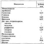 There are vitamins in corn
 Marinated eggplant without sterilization for the winter
 Overdose of vitamin d3
 How much magnesium is in watermelon. What vitamins are in watermelon. Chemical composition of culture
 Kiwi: calories, beneficial properties and harm of kiwi